How we work

Architecture
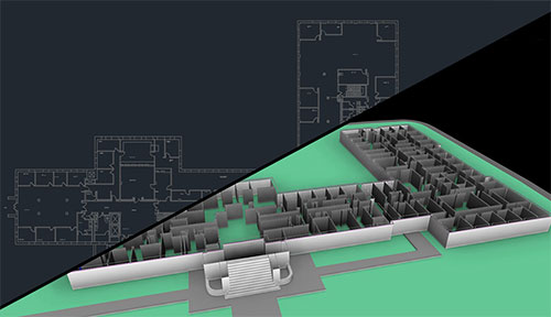
Partitions: Our first step is to draw the partitions of the building. Whenever available, we work with native AutoCAD files to ensure the accuracy of the drawings. We draw partitions and raise them up around 7ft tall, so we easily navigate through the Navisworks™ model and see all trades without having walls blocking our point of view.
Reflected ceiling: To ensure the coordination above ceiling heights, we also draw the RCPs. We draw ceiling tiles and exact lights locations, making sure to avoid any potential clash with recessed lights and allowing for enough access behind them.

Structure
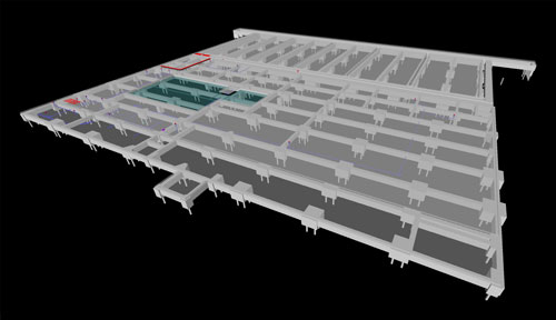
Steel: After the layout of the walls and ceiling, we carefully analyze the contract drawings and draw the beams, joists and columns in 3D as well. This will allow us to make sure that all trades are clash-free with any structural element.
Slab: To ensure there is sufficient space between the trades and the slab, we draw and add the slab in our general 3D as well. We can easily see beam pockets and move the trades to those areas whenever it’s required.

MEP & FP trades
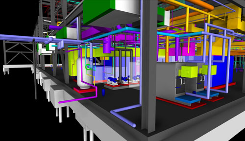
Mechanical, electrical, plumbing, fire protection: Once done with the building layout, we start drawing the trades from the latest drawings received. We draw the trades sizes per contract drawings and the units per approved submittals received.
For the coordination, we start our trades at a general elevation for each of them and try to keep them as flat as possible during the coordination process.

- Equipment per approved submittals, which show proper access for maintenance;
- Sizes of each element of the trades;
- Exact dimensions from grids or walls to each element of the trades;
- Top, bottom, center elevation of the trades, offsets elevations;
- Length of each ductwork section, to allow mechanical contractors to pre-fabricate the ductwork (TDC, slip & drive);
- Reflected ceiling plans with ceiling heights elevations and lights locations;
- Structural beams and joists: sizes, elevations and slopes;
- Sleeves elevations and sizes;
- RFIs (Request For Information) sent in the form of a drawing with textual description of the issue, to request additional component information or report architectural design flaws, such as a lack of ceiling space to run the MEP trades.
